Brief Introduction of Principles of Catalytic Incineration System
The system belongs to centralized heating, the heat source is from the catalytic incineration device, and through the main heat supply pipeline, the heat is delivered in several branches to the regional heat stirring section to mix with the gas from the curing furnace through the automatic heat supply control valve, and is then sprayed out from the PROP air outlet by the heat cycle fan. Each heating section has one set of PID executing mechanism to connect the automatic regulation valve for heat supply through the connecting rod, so as to control the capacity of hot air capacity to reach the temperature control purpose. Due to the application of PID control, the operating temperature of each section of the curing furnace can be controlled within ±2℃. When implementing coating operation, the organic waste gas generated in coating curing enters the catalytic incineration device through waste exhaust pipelines. The organic waste gas from the waste gas pipelines is then subject to waste gas splitting and incising and is divided into several portions, after they evenly enters the surface of the cooling and incendiary cylinders in the heating chamber, they enters the incendiary cylinder to contact with the flame and incinerate. The high-temperature waste gas generated from incineration enters the hot air stirring section through the waste exhaust fan, and after being stirred evenly with the organic waste gas, they are sent to the pre-catalysis splitting and incising device which again incises the high-temperature organic waste gas into several portions and sends it into the catalytic incineration area. Due to the addition of catalyst, the benzene, methylbenzene, xylene and acetone can react with oxygen at low temperature (220-350℃) to have spontaneous combustion and incineration and thus release heat, and the released heat depends on the concentration of oxygen and organic solvent. The high-temperature gas subject to catalytic incineration enters the heat supply pipeline after the secondary heat exchange and is distributed to each heating section to complete the whole catalytic incineration and heat supply process.

Composition of Catalytic Incineration System
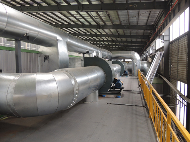
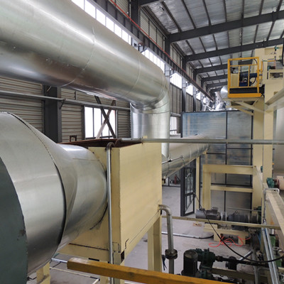
The system is composed of waste exhaust pipeline, waste exhaust fan, catalytic incineration device, heat supply pipeline, sectional heat stirring area, PROP air outlet and curing furnace body etc..
1. Waste exhaust pipeline: (waste exhaust opening, manual regulation valve for waste exhaust, waste exhaust branch pipe, waste exhaust mains).
2. Waste exhaust fan: the fan power is matched according to the actual conditions.
3. Catalytic incineration device: (waste gas splitting and incising and heat exchange section, incinerating and heating section, waste exhaust fan, hot air stirring section, pre-catalysis gas splitting and incising and heat exchange device, catalytic incineration section 1, catalytic incineration section 2, catalytic incineration section 3 and heat exchange section).
4. Heat supply pipeline: (heat supply mains, heat supply automatic regulation valve, heat supply branch pipe).
5. Sectional heat stirring section: (heat stirring section, heat circulating fan).
6. PROP air outlet: the outlet quantity and outlet size are matched according to the actual conditions.
7. Curing furnace body: the length is matched according to the actual conditions.
Purpose
The product is used to empty the incinerated waste gases of benzene, toluene, xylene and naphthalene etc. in the ferrous-printing and color-plate coatings industry, and apply the heat released thereby to the centralized heating of the drying room. Such product uses a single high-power combustion engine for centralized heating instead of multiple small-power combustion engines of the original production line, which can make full use of the organic solvent in the waste gas to burn and release heat for heat supply in the drying room on the basis of ensuring the flue gas emission to meet the environmental protection requirements. It is not only applicable to the waste gas treatment and heat energy recycling of the coating drying rooms in the industries of metal printing, color-steel plate, aluminum plate and aluminum strips etc., but also applicable to the waste gas treatment and heat energy recycling of the coating production lines of various specifications of industries of automobiles and motorcycles etc..

Characteristics
1.High purification efficiency: mixed waste gases, even air distribution and stable temperature control improve the purification efficiency, reaching and exceeding the national standard GB16297-1996.
2.Significant energy-saving effect: it directly returns the heat generated from high-temperature incineration to the drying room for energy recycling, making the energy-saving efficiency up to 15%-35%.
3.Good safety performance: the furnace body is equipped with explosive door to release deflagration pressure, and adopts sectional micro-negative pressure combustion, with no temper.
4.Good thermal insulation performance: the system uses plug-in stainless fan and 200mm thick heat insulation layer, with less heat dissipation, and the surface temperature is less than or equal to the room temperature of +20℃.
5.High automation control degree: it completely substitutes the original temperature control in drying room, and with the one-key start, it can be subject to whole-process and full-automatic operation, and there are safety protection devices of over-temperature alarm, low-temperature alarm and flame failure alarm lights to guarantee the device in stable operation.


